An A & P IA Aircraft Mechanic Goes Through the Aircraft Engine Overhaul Process
Things wear out, things deteriorate and things break. If this is true in any industry, it is even more true in aviation. Aircraft need constant repair, inspection, and upkeep whether they get used or not. In fact, it’s a common theory that aircraft have more problems and need more repair when they are not used regularly.
Airframes and aircraft engines are carefully inspected, adjusted and tested at each annual or 100-hour inspection. And often, a number of problems are discovered and repaired during this yearly event.
When an engine is inspected, we look for any condition that could affect its reliability and airworthiness. Of course, one of the most well known and discussed procedures we perform is a compression test. This commonly is mistakenly considered the measure of health for an engine. While it is true this test offers some very valuable data about cylinder life, it is far from the basis for determining the condition of an engine. The truth is that the things that make an aircraft engine unsafe usually are found deeper inside the engine, rather than in the cylinders themselves.
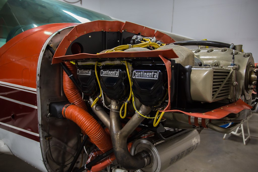
Recently one of my clients asked me to perform an aircraft engine overhaul on the engine in his Cessna 182. The engine was beyond the recommended time period for overhaul both in hours and calendar time. The engine had been barely passing the requirements for compression tests and had begun to have higher oil consumption. It also had a tendency to quickly turn the oil black after oil changes and emit a pungent smell. This condition occurs when compression gasses leak past the rings and scorch the oil down inside the crankcase. This changes the composition of the oil, and causes oil to lose some of its lubricating and cooling capabilities.
According to the log books, the engine had not been apart since the 90’s when it had its last aircraft engine overhaul. All things considered, we knew it was time. Plans were made to begin the process once the owner had put some money away.
We expected to find plenty wrong inside the engine, and were surprised to see that although there was a lot of wear and tear and deterioration, there were no looming disasters. There was nothing that would have developed into an engine failure in the foreseeable future, unless something unexpectedly broke.
Coincidentally, a few weeks after starting the 182 project, a local 172 flight school aircraft developed problems with its past TBO engine. This Lycoming engine had been used and abused by students for a long time, and eventually started running rough one day. It had been leaking oil excessively over the last few hours, and I made the determination that it was time to ground it no matter what the rough running condition was.
The busy flight school was not thrilled to have it go offline, but I felt strongly that it was time.
I also expected to find a lot wrong inside this engine. I was not surprised to find some more serious problems as we took it apart, confirming my concerns about its airworthiness.
These two projects provide some good examples of what goes wrong inside aircraft engines, and I decided to photograph and document them to share with others who might be interested. What follows are observations and information I have gathered over the years. I wish I had all the knowledge of those guys who perform aircraft engine overhaul after aircraft engine overhaul, day in and day out. But since my attention gets divided between a lot of other brain cell absorbing subjects, I will offer what I have and nothing more. I generally overhaul a couple of engines each year, either for myself or for clients, and occasionally do prop strike inspections. I always send out any parts that need machine work or specialized inspections, like magnufluxing, to reputable shops that do that type of work. My job is then to make sure the parts go back together properly.
I have been messing with engines for my entire adult life and find them to be fascinating. I sometimes think back to the very first engine I “overhauled”, when I was a senior in high school. It was the engine out of my GMC pickup truck, and I had decided to tear it apart and rebuild it because it sounded fun. Mostly, I wanted to see what was inside that engine. I bought a set of rings, bearings and gaskets and went to work with no idea what I was doing. Even the shop teacher couldn’t figure out what the problem was when I put the first piston and connecting rod in. No matter how big a cheater bar we got, we could not turn the engine once I tightened the bolts. Everyone said it would be tight, and it certainly was. Turned out, I had unknowingly bought bearings that were oversized by .030 inch. As soon as the nuts were just more than hand tight, it clamped down on the crankshaft with enough force it would never turn, no matter how hard I tried. Since then, I have had some good teachers and a lot of experience that has taught me much, and I feel confident in my ability to assemble an engine.
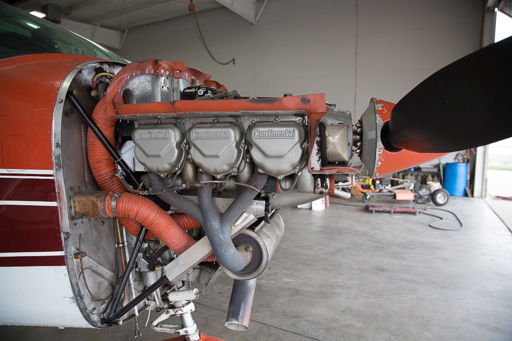
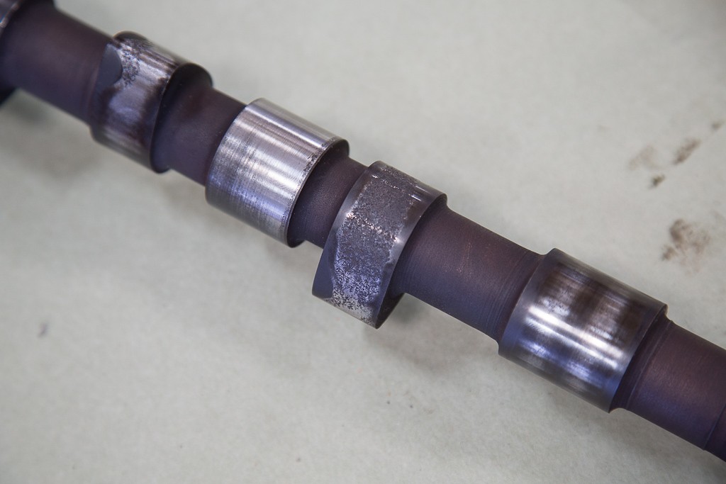
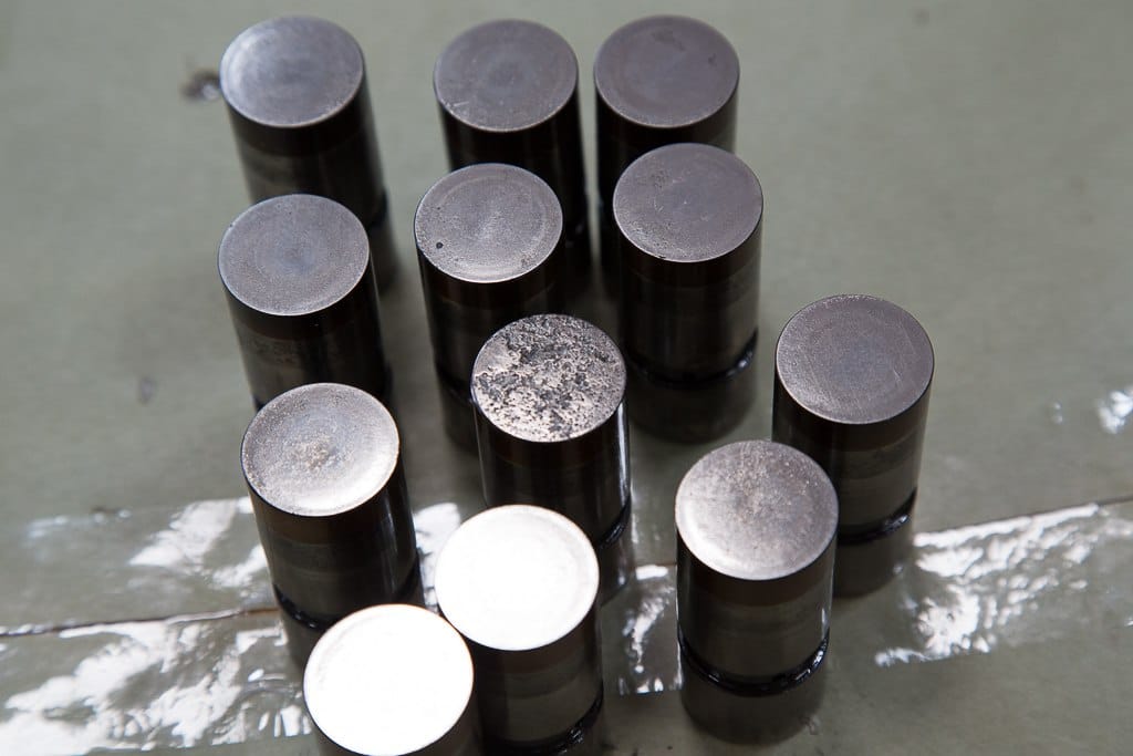
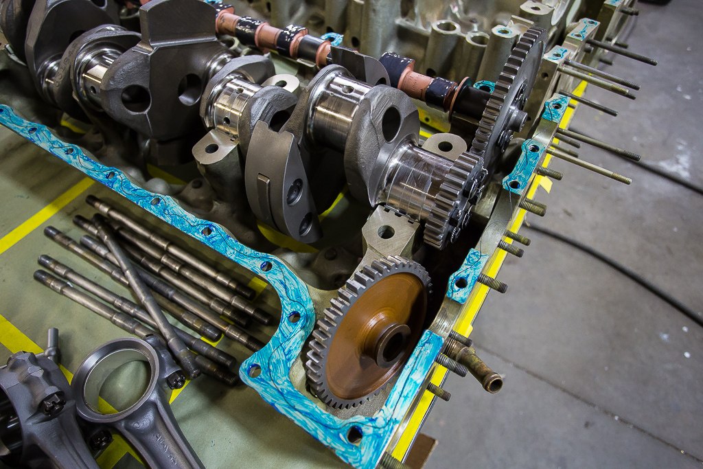
When we tore the 182’s Continental engine down, we found a number of conditions that needed repair. But as I indicated, there was nothing that made me think it would have been unsafe to fly for the foreseeable future. The problems inside this engine were generally a result of irregular use. The camshaft, lifters and oil pump gears were badly corroded from rust that had accumulated on these parts. Once rust is present, it becomes an abrasive between the parts as they work together. Over time, the hardened surfaces begin to wear off, exposing the softer metal below. Pitting and accelerated wear occurs, and if left too long, the parts become damaged beyond repair and will require replacement. As can be seen in these photos, the camshaft and lifters were pitted and corroded and had to be scrapped.
The inside of the aircraft engine is subject to its own atmospheric climate that can be very hazardous to the internal steel parts it contains. When the engine is warmed up and cooled down in the normal routine of operation, there can be a significant amount of condensation that accumulates inside. This happens even more when humidity is high or outside temperatures are cold. Some people use engine heaters to warm the engine before start up on a cold day, and find them helpful because the aircraft starts easier and oil flows sooner to critical parts of the engine. However, these heaters should never be left on for long periods of time. This causes condensation to accumulate inside the engine, promoting rust where the internal components can be damaged quickly.
Some pilots believe that periodic start-ups and ground running the engine to warm it up occasionally is good for it during periods of inactivity. They will run the engine for 15 minutes or so on the ground to get the oil flowing and warm the engine. This is actually one of the worst things you can do for your engine, because it doesn’t normally get the temperature up to operating ranges where moisture can be eliminated. Ground running also can be damaging to the aircraft engine because airflow over the engine is not adequate to properly cool the cylinders. The very best thing you could do for your engine is to fly it once a week, long enough to get the temperature up to the normal range. In certain climates where humidity is high, this problem can be more serious than in other areas, and the consequences of not flying your aircraft are more severe.
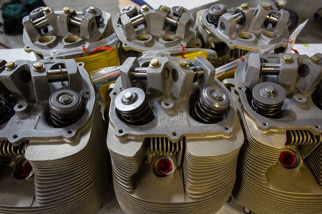
The cylinder assemblies from the 182 were, as expected, well worn. Continental cylinders typically begin to wear most critically in the exhaust valve guide area. Many believe that the reduced amount of lead in avgas has been one of the major reasons for accelerated wear in the valve guide area. When this happens, the valve becomes loose in its guide and the critical metal to metal seal becomes compromised, allowing leakage of exhaust gasses past the area. It doesn’t take long for this hot gas to erode the valve and seal area. The cylinder barrels and piston rings also wear over time, and at some point, hot compression gasses begin leaking past. This causes a loss of power and scorched oil as described above. This engine was generally worn, and ready for overhaul, but again, probably not so far as to be dangerous.
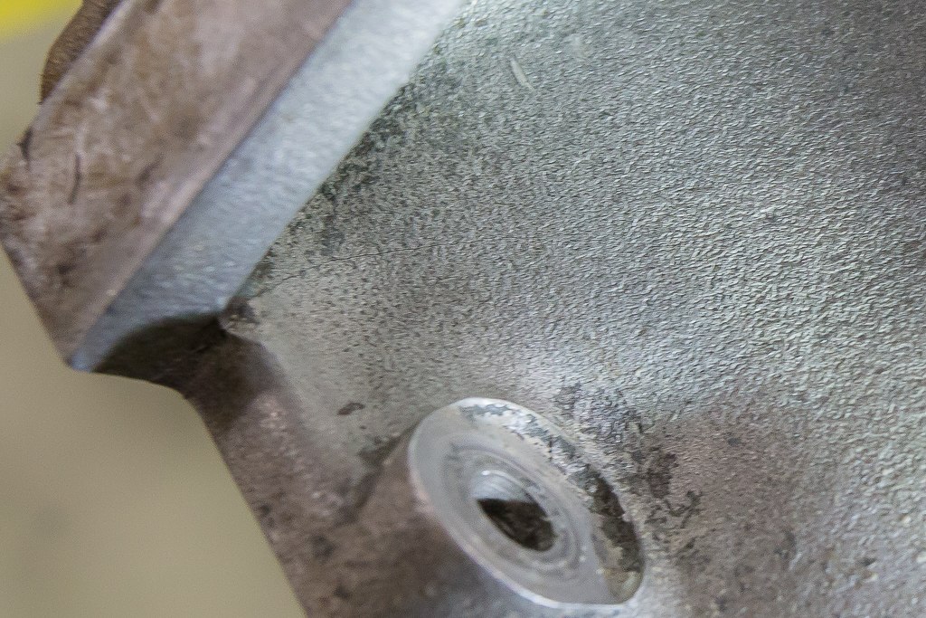
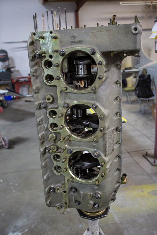
We found more serious problems in the Lycoming engine. It had seen more regular use through its life, but in a flight school environment, where it had been subjected to plenty of hard use. These aircraft and their engines usually get plenty of abuse. Students start them in cold weather, run them hard in extreme summer temperatures, do endless touch and goes with major power changes and make all the normal mistakes as they learn everything that a pilot needs to know. This engine had a lot of wear, especially in the main and connecting rod bearings, but the real problem we found was in the crankcase. We spotted a couple of large cracks in the area below the aft cylinders. One crack was very visible to the naked eye. This offered an easy explanation for the ongoing pesky oil leaks we had been dealing with for awhile. I’m not sure how the cracks had developed, but I do have one idea.
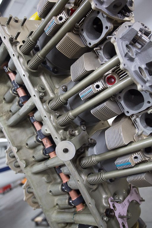
A few months ago when the aircraft first came to the new flight school at our airport, it was seriously leaking oil. This oil then dripped onto the exhaust system, causing a lot of smoke, especially when the heater was turned on. We investigated the problem and eventually removed a cylinder because the leak was coming from its base. Once the cylinder came off, the answer was obvious. Someone had left a thin washer on one of the mounting studs. Surely this was an oversight when the engine had been assembled. Often the crankcase halves are initially held together with washers and nuts until cylinders get installed. Whoever did the work must have not seen the washer, and installed the cylinder and tightened up the nuts without removing it. This would have put a high amount of uneven pressure on the strong but fragile aluminum crankcase. It’s made very strong to withstand pressures in the way they normally occur in an aircraft engine, but fragile and weak when stressed in ways it’s not designed to withstand. Cracks can also occur from other conditions like rapid temperature changes, detonation, use of improper fuel or impact damage from accidents.
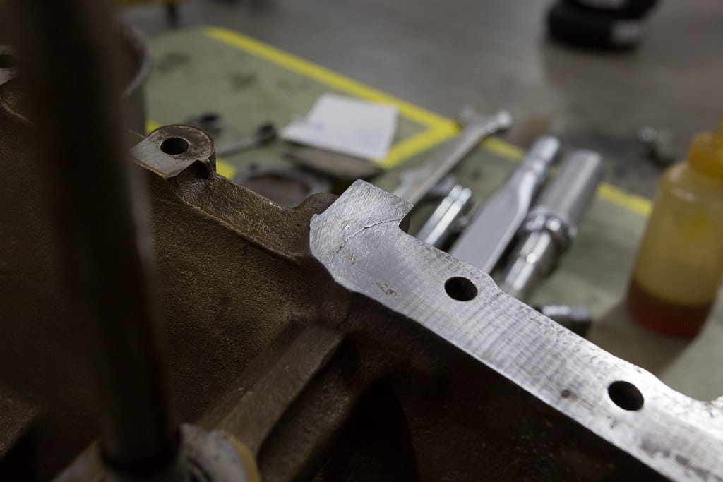
I sent the crankcase to a facility that specializes in the repair of conditions like this. Usually, the cracks are expertly welded, followed by a machining process to make the mating surfaces perfectly flat. The case halves are then bolted together and a boring bar is then run down through the middle where the crankshaft and camshaft are housed. This process makes those holes perfectly aligned and sized. All this makes the case dimensionally like new.
Sadly, things didn’t go as planned with the repair of our crankcase. The cracks were too big and as the welder began doing his job, the cracks simply became bigger. Finally, the case was determined to be un-repairable and was scrapped. This meant I had to go shopping for a replacement, resulting in a time delay and a major hit to the budget.
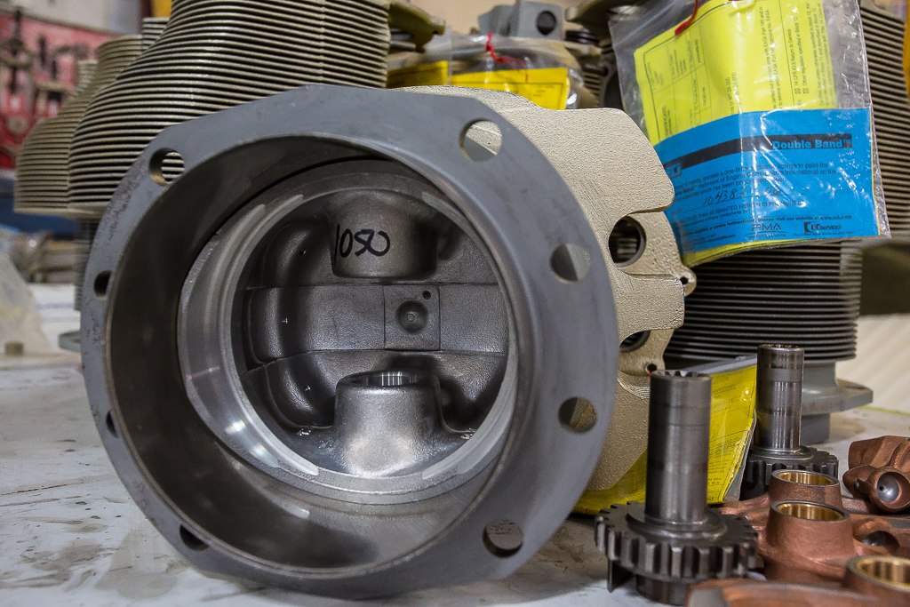
The crankshaft, camshaft, tappet bodies, connecting rods and rocker arms were all sent to another shop for rework and certification. Due to wear, the crankshaft journals had to be reground to a slightly undersized and perfectly round condition. This would mean the new bearings that were installed would need to be oversized to account for the material removed from the crankshaft. The camshaft and tappet bodies were reground and shaped back to their original profile, as they were when they were new. Each of the internal steel gears and shafts were tested for cracks and inspected for damage and wear. Most passed, except the crankshaft gear, which was rejected for pitting and wear on the teeth. The connecting rods also failed the certification because the width of the bearing end on them was below the specifications supplied by the manufacturer. I am not certain why this was the case, but we were forced to find a set of used but certified replacements. In most instances, parts that need to be acquired are much more economical if used but certified ones can be located. New parts are often so expensive that this is the only reasonable alternative.
During the time all the internal engine parts are out being worked on, we clean, inspect and repair the remaining parts. I also order a set of rebuilt cylinder assemblies. In my opinion, this is the simplest and most predictable way to deal with cylinder work and it is generally comparable price wise. They come completely ready to install, with pistons and rings assembled. This saves time and I don’t have to worry about unforeseen problems that cause delay and increased costs.
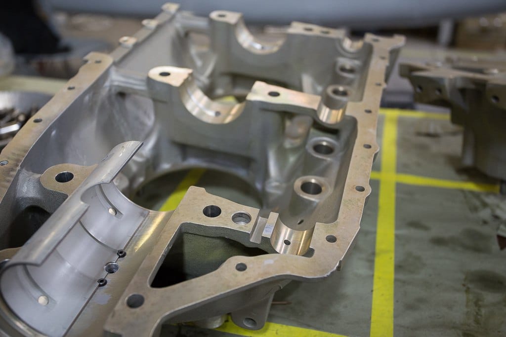
Assembly for both the engines I have been talking about is similar and most techniques are the same. Once all the parts are on hand, I clear off a good work space where everything can be organized. The first step is to clean everything and inspect all the parts for any damage that may have occurred during shipment. I also carefully look for anything abnormal or missing. Once satisfied, I lay out the crankcase halves and insert the main bearings. They simply push into place and are then held in place by tangs. Now the two halves are carefully put together. Through studs are driven into the case with a brass hammer, and nuts installed on each side with washers to protect the soft aluminum. These through studs not only hold the aircraft engine together but align the case perfectly to keep everything precisely centered. The nuts now get tightened in a proper sequence, to torque values listed in the manufactures aircraft engine overhaul manual. A telescoping instrument that is spring loaded is carefully positioned inside each bearing location. The device locks the distance it spans when removed from the bearing cavity. Using a micrometer, this value is then measured and recorded. This is followed by a measurement of the crankshaft pin that will ride in that bearing. The difference between the two is called the clearance, and generally should be .002-.003 inch. In service, with proper oil pressure, this clearance will fill with oil and will provide a perfect film, so there is no metal to metal rubbing. Each of the main bearings are measured the same way, followed by a similar procedure with the connecting rods.
Once satisfied that the clearances are all equal to the specifications in the aircraft engine overhaul manual, the crankcase can be disassembled and prepped for final assembly. This means a liberal amount of assembly lube is applied to each bearing surface, including the camshaft supports. Surprising to most who are familiar with automobile engines, you wont find bearing inserts for the camshaft on aircraft engines (at least common Lycoming and Continental engines.)
Tappet bodies on the Lycoming engine have shoulders and must be installed before the case goes together. With this in mind, the cam is laid inside one-half the case, on top of the installed tappets. It is then temporarily held in place by wrapping wire around it, and secured to an outside stud. The crankshaft is put in place in the other case half, and then the cam side case half is turned upside down and placed on the other half. Through studs are driven in once again, washers and nuts are snugged up and the engine is then installed nose down on an engine stand. The manual suggests connecting rods be installed on the crankshaft before the crankcase is assembled. However, I generally find it less cumbersome and easier to install them after the engine is up on the stand. I have never found a real answer as to why manufacturers direct otherwise.
Once the rods are installed, the nuts torqued and cotter pinned, if applicable, the cylinder assemblies can be installed. This is when visual progress is at its peak because all the cylinders can be installed quickly. Pistons already installed into the cylinders are pulled out just far enough to slide a new piston pin in place. New O rings are put on the bases of the cylinders. The cylinder/piston assembly then quickly goes into place by sliding the pin through the piston and connecting rod, followed by pushing the cylinder into place and installing the hold down nuts which are only snugged. Once all the cylinders are installed, they are carefully torqued in a particular sequence with special wrenches designed to reach around cylinders. This is an important part of an engine rebuild. Not only does this torque hold the engine and cylinders together with the proper squeeze on the main bearings, the sequence of tightening ensures the aluminum case halves do not warp or distort in any way. It brings them together perfectly, so there is no stress and so they can seal properly. The process of tightening is a little tedious and time consuming because of the several stages and large amount of fasteners. Once this is done, though, I always feel like the hard part is over and the rest goes fairly easy.
This doesn’t mean the job is nearly finished, though. There are still a lot of components to be installed, including the oil sump, gears, oil pump, accessory housing and so on. The hydraulic lifters are also installed along with pushrods, rocker arms, and pushrod housings. When this part of the valve train is assembled, the dry tappet clearance must be checked. This is simply a process to make sure there is the correct amount of lash or looseness between the rocker arm and valve stem. It has to be done with the lifter collapsed, meaning it has not been filled with oil. The hydraulic lifter’s job is to transfer a lateral movement from the camshaft through the pushrod and rocker arm, to move the valve open and closed. The hydraulic portion simply keeps a zero clearance in the system by filling with oil to take up the distance. These lifters bleed down at certain pressure points to avoid filling too much, which would not allow the valve to close completely.
With the basic aircraft engine assembled, a new or rebuilt set of magnetos, ignition harness, and spark plugs can be installed. Slick mags are not economical to overhaul because of the high cost of parts. As a result, new ones are purchased. Bendix mags can usually be rebuilt economically. I send them to a facility for this work. They have the proper equipment to test them and they do this type of job every day.
The engine is ready for installation now. New engine mounts and fluid hoses are obtained, and an overhauled carburetor is installed. The propeller and governor have been overhauled and installed. Baffle seals are repaired or replaced as necessary. It’s very important to make sure every detail is covered to ensure the best airflow for cooling is provided for the new engine. There are always plenty of areas that need work as the task progresses and so the job sometimes seems never ending. I like to make everything look as new as possible from the firewall forward. This is the best time to repair all the things that are worn or deteriorated. It’s also a nice time to install new engine control cables. They are relatively easy to install during the engine installation and hard to do later. The 182 owner elected to have us install a new engine monitor during the job, and a number of hours were spent routing all the sensor wiring and installing the display in the instrument panel. We also plumbed in a transducer for the fuel flow instrumentation that was a part of the monitor. This is another job that is easier to do during an engine installation than other times.
With everything installed, everything cleaned up and everything repaired, it’s time to add oil and complete all the final preparations to run the engine for the first time. Oil pressure should be obtained prior to this first run, and this is completed by spinning the propeller by hand for a number of revolutions, followed by cranking the engine with the starter motor with spark plugs removed. When pressure is indicated on the gauge, the spark plugs can be reinstalled.
The engine is now ready for its first run. I always have an assistant observe while I run the engine for this first time. If anything appears abnormal or leaks are observed, I get a signal to quickly shut down the engine. If everything is doing OK, I run the engine for about 5 minutes or less and check the magneto drop, the charging system and the general operation of the aircraft engine.
If all goes well for the test run, it’s time to cowl the engine and do one more short test run to a higher power. This is to double check operation, followed by one more inspection for leaks. A test flight is now in order. For me, I like to spend about 15 minutes in the pattern at high power and then land to carefully inspect the engine. Commonly, oil leaks don’t show up until the aircraft is flown. If all is well, it’s time to go put a couple hours of flight time on the engine. Power settings should be as high as possible without overheating the engine. This gives the best opportunity for the engine to be properly broken in. During the flight, I make occasional small power changes either by manifold pressure or RPM to avoid continuous operation at one power setting. I am not certain why engine builders recommend this, but I have always had good luck with my procedures, so I will keep doing it. Touch and goes should be avoided for the first 3 to 5 hours during this initial break in. Once the engine has 5 hours on it, you can operate it the way you normally run the airplane. Although there are differing opinions, most still seem to agree that mineral oil should be run for the first 25-30 hours. After this time, your regular flavor can be put back in, assuming oil consumption is not excessive.
Rebuilding the engine on your aircraft is no small task and the cost associated can be staggering. With proper care and upkeep, the investment will be one that lasts for a long time and will provide safe and reliable power for your aircraft.